"DVD Recording"
Alright, I know that many of you may say that there are plenty of DVD burning progs out there and that if I do a guide like this I should cover all of them. But I only got Nero and many users are asking me about how to burn a DVD-Video with Nero, so that's why Nero is the one for the guide.This guide is supposed to be used by people that have created the compressed DVD files using DVD Shrink and now they don't know what to do with them or everyone that wants to see how to create a DVD-Video. Remember that for the DVD Decrypter guide you don't need Nero, as DVD Decrypter can burn the ISO file itself. Anyway before start reading this guide keep in mind that it is for use with DVD Shrink or other program that creates .IFO and .VOB files. Don't use it to burn files or mp3 in your DVD, for this you need to select a DVD-ISO disc.Of course, Nero Burning ROM is a commercial program and we don't have it available for download. Instead you can get a trial version here.
*First of all I make clear that I use version 6. If you have an older version that supports DVD (I think all the versions after 5.5.x.x) then the process is the same. Please make sure you start Nero Buring ROM I show here and NOT the Nero SmartStart
*The new complication comes up. If you see a Wizard close it (there must be a button down right which says Close Wizard or something). Open the pull-down menu I show and select DVD.
NOTE: If there is no pull-down menu then your version does not support DVD
*Select DVD-Video (1) from the list. Then just make sure the settings (2) are the same as shown here. Then click on the Label tab.
*Here just put the label that you want your DVD to have. (It's the name that you see before your drive's letter every time you go to My Computer). After that click New.
*
Thursday
Monday
Package type
FC-PGA Package Type
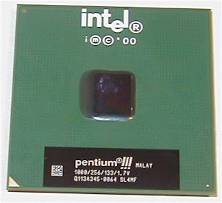
FC-PGA Package TypeThe FC-PGA package is short for flip chip pin grid array, which have pins that are inserted into a socket. These chips are turned upside down so that the die or the part of the processor that makes up the computer chip is exposed on the top of the processor. By having the die exposed allows the thermal solution can be applied directly to the die, which allows for more efficient cooling of the chip. To enhance the performance of the package by decoupling the power and ground signals, FC-PGA processors have discrete capacitors and resistors on the bottom of the processor, in the capacitor placement area (center of processor). The pins on the bottom of the chip are staggered. In addition, the pins are arranged in a way that the processor can only be inserted one way into the socket. The FC-PGA package is used in Pentium® III and Intel® Celeron® processors, which use 370 pins.
FC-LGA4 Package Type
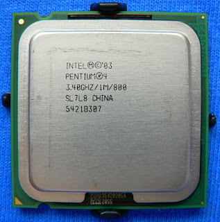
FC-LGA4 Package TypeThe FC-LGA4 package is used with Pentium® 4 processors designed for the LGA775 socket. FC-LGA4 is short for Flip Chip Land Grid Array 4. FC (Flip Chip) means that the processor die is on top of the substrate on the opposite side from the LAND contacts. LGA (LAND Grid Array) refers to how the processor die is attached to the substrate. The number 4 stands for the revision number of the package.This package consists of a processor core mounted on a substrate land-carrier. An integrated Heat Spreader (IHS) is attached to the package substrate and core and serves as the mating surface for the processor component thermal solution such as a heatsink.You may also see references to processors in the 775-LAND package. This refers to the number of contacts that the new package contains that interface with the LGA775 socket.The pictures below include the LAND Slide Cover (LSC). This black cover protects the processor contacts from damage and contamination and should be retained and placed on the processor whenever it is removed from the LGA775 socket.
FC-PGA2 Package Type

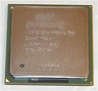
FC-PGA2 Package TypeFC-PGA2 packages are similar to the FC-PGA package type, except these processors also have an Integrated Heat Sink (IHS). The integrated heat sink is attached directly to the die of the processor during manufacturing. Since the IHS makes a good thermal contact with the die and it offers a larger surface area for better heat dissipation, it can significantly increase thermal conductivity. The FC-PGA2 package is used in Pentium III and Intel Celeron processor (370 pins) and the
Pentium 4 processor (478 pins)
Wednesday
Motherboard form factor
Motherboard Form Factors
The form factor determines the general layout, size, and feature placement on a motherboard. Different form factors usually require different style cases. Differences between form factors can include; physical size and shape, mounting hole location, feature placement, power supply connectors, and others.
ATX
ATX was developed as an evolution of the Baby AT form factor and was defined to address four areas of improvement: enhanced ease of use, better support for current and future I/O, better support for current and future processor technology, and reduced total system cost.

The ATX is basically a Baby AT rotated 90 degrees and providing a new mounting configuration for the power supply. The processor is relocated away from the expansion slots, allowing them to hold full length add-in cards. The longer side of the board is used to host more on-board I/O. The ATX power supply, rather than blowing air out of the chassis, as in most Baby AT platforms, provides air-flow through the chassis and across the processor.
Mini-ATX
This form factor is basically the same as ATX with a smaller allowable board size.
- ATX = 12" x 9.6"
- Mini-ATX = 11.2" x 8.2"
microATX
This form factor was developed as a natural evolution of the ATX form factor to address new market trends and PC technologies. microATX supports:
- Current processor technologies
- The transition to newer processor technologies
- AGP high performance graphics solutions
- Smaller motherboard size
- Smaller power supply form factor

FlexATX
A subset of the microATX design. FlexATX offers the opportunity for system developers to create many new personal computer designs. FlexATX allows enhanced flexibility where conforming motherboards may be enclosed; that is, all-in-one computing devices, LCD-personal computers, or standard desktop systems.
This form factor is designed to allow very custom case and board designs to be manufactured. For example; The NBA could commission computers that looked like basketballs. There is not too much limit on the shape of the board and case. We should see some very interesting system designs emerging from this form factor.
- Supports current socketed processor technologies
- Smaller motherboard size
- ATX 2.03 I/O panel
- Same mounting holes as microATX
- Socket only processors to keep the size small
LPX & Mini LPX
This is based on a design by Western Digital. The expansion slots are on a single riser card which is mounted onto the planar board. Mainly OEM manufacturers (i.e. Packard Bell/NEC, Dell, etc) use these boards.
LPX is an older form factor (8.67" x 9.25") that has been replaced by NLX. The LPX form factor is usually found in desktop model PCs. The LPX case is a slim-line, low-profile case with a riser card arrangement for expansion cards. This means that expansion boards are parallel to the motherboard, rather than perpendicular to it as in other common form factors, such as AT and ATX. This allows for smaller cases, but limits the number of expansion slots, usually to two or three.
LPX motherboards often have the video adapters integrated onto the motherboard, and they may have integrated sound as well. This can provide a high-quality product at low cost, but can make upgrading or repair difficult. It is not always possible to disable the built-in video adapter cards to allow for an upgrade. LPX motherboards also usually come with serial, parallel, and mouse connectors attached to them, like ATX.
The LPX case and motherboard design are not designed for a home PC builder, as they can be cramped and difficult to work in, as well as being non-standard. They also offer poor expandability, poor upgradability, poor cooling, and difficulty of use for the home PC builder.
NLX
NLX is a new low profile motherboard form factor designed to improve upon today’s low profile form factors and to adapt to new market trends and PC technologies. NLX does the following:
- Supports current and future processor technologies
- Supports new Accelerated Graphics Port (A.G.P.) high performance graphics solutions
- Supports tall memory technology
- Provides more system level design and integration flexibility; for example, the new design flexibility allows system designers to implement a motherboard that can be removed quickly, in most cases without removing screws, thus lowering the PC’s total cost of ownership.

The picture above shows an example of an NLX board and riser.
- The add-in card riser is located at the right edge of the motherboard (as viewed from the front).
- The processor is located at the front, left section of the motherboard, improving thermal and clearance issues.
- Taller components such as the processor and tall memory are preferred to be located on the left side of the motherboard, allowing the I/O slots to hold full length add-in cards in many system configurations.
- At the back of the motherboard (as viewed from the front), the I/O connectors are stacked single and double high to support more connectors.

Several major PC vendors world-wide worked jointly to define the NLX form factor and to incorporate flexibility to accommodate the best designs for current and future PCs. NLX is a public specification intended for widespread use in many types of systems.
Tuesday
Installation in windows XP2000
The first method is the easier of the two. But if by any chance, you descide to Hibernate your computer while in WindowsXP for example, then your MBR is overwritten by windowsXP and you will be unable to boot into linux using your bootloader.
Here I will explain how to overcome this setback by using the second method. That is installing the bootloader (LILO or Grub) on the linux partition . Here I am explaining the steps with respect to RedHat Fedora Core 2 distribution. But the steps are equally valid for any linux distribution. This is the procedure to follow:
Install WindowsXP/2000 first.
Now install Fedora core 2. I installed it in /dev/hda3 ; which was my linux ext3 partition.
While installing, enforce LBA32. This is necessary only if you intend to install the bootloader in a partition above 32GB. In my case (I have only 12 GB total) it was not necessary.
At the section where the installer asks whether you want to install a boot loader; select yes (Fedora comes with Grub as default boot loader) and in the advanced settings, select your linux partition as the place to install the bootloader. In my case it was /dev/hda3. Nowcomplete the Fedora core 2 install.
Reboot the computer and load again from the first CD in your Fedora Core 2 distribution.
At the boot prompt, type:
Procedure in installation windows98
3Com (R) Corporation EtherDisk (R) Diskette for the3C90X EtherLink XL 10/100 / EtherLink XL NIC FamilyWindows 98 Information
First time installation of Windows 98
Windows 98 has the built-in ability to support the EtherLink XL family of NICs. Unfortunately, even though Windows 98 is a new product, the EtherLink XL driver that comes with Windows 98 is quite old and may not work well under some conditions. To avoid installing the driver on Windows 98 and install the EtherDisk 4.0 software, follow the steps below.
Do not install the NIC! Install Windows 98 before you install the NIC.
Run PREINSTL on EtherDisk #1. This step prevents Windows 98 from identifying the NIC so it will prompt for external media. Shut down the computer.
Install the NIC and start the computer. Make sure the NIC is connected to the network.
Start Windows 98. During the boot up, Windows 98 will display a screen showing that a PCI NIC has been detected. Put EtherDisk #1 into the floppy drive and press "next".
Windows 98 will read the EtherDisk and display the name of the NIC. Press "next". Windows 98 will continue to read the EtherDisk, then prompt for EtherDisk #2. Insert EtherDisk #2 in the floppy drive, then press "OK". Windows 98 reads files from EtherDisk #2. Windows 98 then reads files from the Windows 98 installation media, and returns to the add new hardware wizard. Press the "finish" button. If Windows 98 cannot find the Windows 98 installion media, it will prompt you for the path to the media (CD_ROM, etc). You must provide this path for the install to work successfully.
Windows 98 then displays the message "Do you want to restart your computer now?". Press the "yes" button.
The computer will reboot. When the system has booted up, the network is ready to use.
Updating from Windows 95 to Windows 98 with a 3C905 or 3C900 NIC
If you have a 3C905 or 3C900 NIC installed, you must follow the steps below to successfully upgrade from Windows 95 to Windows 98.
With Windows 95 running, open the start menu, settings, control panel. On the control panel screen, double click the "network" icon. On the network configuration menu, choose the "3Com EtherLink XL" NIC, and press the "delete" button. Deleting the NIC may delete all network components, so record the configuration settings of the other network components that may be needed when the NIC is reinstalled later. These include the TCP/IP protocol stack settings, if present.
Shut down the computer and remove the NIC. Reboot Windows 95, install Windows 98, and go to step 1 under "First Time Installation of Windows 98" above.
How to recover if the procedures above were not followed
The recovery from not following the procedures above are listed below. The recovery method varies. Each scenario is listed below by path to arrival, problem symptoms, and recovery procedure.
Fresh install of Windows 98 with a 3C905B or 3C900B NIC installed
The problem is network software is not installed and the 3C90XB NIC is not detected on subsequent boots of the operating system.
When Windows 98 installs, if it detects a device it does not have drivers for, that device is put in the unsupported device class "other". This step prevents the NIC from being detected again.
To fix this problem, right mouse button click the My Computer icon, choose "Properties". On the System Properties page, select the "Device Manager" tab. Press the small box with the "+" symbol next to "Other Devices". Select "PCI Ethernet Controller" located under "Other Devices" and press the Properties button at the bottom of the menu. On the PCI Ethernet Controller Properties screen, select the "Driver" tab, then press the "Update Driver" button. This launches the Update Device Driver Wizard. Press the "Next" button. Press the "Next" button on the next screen. Put EtherDisk 4.0 diskette #1 in the floppy disk drive. On the next screen, check the "Floppy disk drives" check box and press "Next". The Wizard will read the diskette and detect a match for the NIC. Now follow the installation procedure from step 5 under First Time Installation of Windows 98 above.
Fresh install of Windows 98 with a 3C905 or 3C900 NIC installed
Friday
PCI slots

PCI is short for Peripheral Component Interconnect. The PCI slot is a local system bus standard that was introduced by the Intel Corporation, however, it is not exclusive to any form of processors and PCI slots are found in both Windows PCs and Macs. PCI slots allow numerous different types of expansion cards to be connected inside a computer to extend the computers functionality. Examples of PCI expansion cards are network cards, graphics cards and sound cards
Subscribe to:
Posts (Atom)
